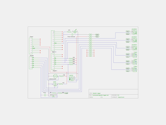
There are a few features I want to add to the Garden Logger, but now the wiring's getting complicated. I'm adding three soil moisture sensors, a battery voltage measurement circuit, a voltage reference, and an LED with an annunciator. I need to use a CAD tool to draw the schematic, so I tried gEDA Schematic Editor. It's pretty easy to use and there is a library of user generated parts. You can also easily generate your own parts and modify existing ones. I used the symbol editor to create a soil moisture probe and a temperature/humidity sensor. Once you've created the symbol, you have to move it to /usr/share/gEDA/sym/local.
For the battery voltage measurement circuit, I needed to calculate what resistor values to use for the voltage divider. I wrote a little script to calculate this, and in the process found a neat library called "engineering_notation". The library makes it easy to display values in powers of three using the correct SI notation.
Here are the results:
Enter input voltage: 15
Enter output voltage: 5
Enter current in mA: 1
r1 value => 10kΩ
r2 value => 5kΩ
voltage => 5.0 volts
current => 1.0 milliamps
r source => 2.50kΩ
r1 power => 10.0 milliwatts
r2 power => 5.0 milliwatts


