Sunday, July 8, 2018

Grafting Fruit Trees

I've always thought grafting was an amazing bio-hack. It seemed like an incredibly difficult task to get a branch from one tree to grow on another. It turns out it's not that hard, especially because there are a lot of resources available. If you search the web for examples, though, you'll be overwhelmed by all the different techniques. But first, where do you get cuttings to graft onto you trees. What we did was to go to a scion exchange. This is where you pay $5 for admission and can take any scions, or fruit tree cuttings, that you want to try grafting. There are also demonstrations of techniques that work for the types of trees in your area that you want to graft. After you've selected a technique, you can then search for more information and videos.

We tried both bark grafting and cleft grafting. I think the cleft graft is much easier, but it requires cutting toward yourself, so you have to be extremely careful. I used a very sharp grafting knife and put a spool around the root stock to protect my hand, but even that was very scary.

We did grafts on apples, pit fruits, pears, and citrus in two grafting sessions. A little more than half of the grafts were successful. Not bad for a first try. Apples and pit fruits were easier. Citrus trees were more difficult. Some of the fastest growing grafts were onto a volunteer nectarine tree - it must have grown from a pit I tossed into the back yard. The fruits on these tree have never been good, so it was a good candidate for grafting.

Here's a photo of the nectarine a couple of months after the graft:


And here's a photo of a Meyer lemon on Eureka lemon root stock.


Unfortunately, in many cases I can't tell you what the scion is until after we have a harvest because I tagged it with Sharpie on plastic and the weather faded it to unreadability! Scratching the name of the scion type onto an aluminum tag works much better.


Tuesday, April 17, 2018

Groundplane Antenna

I got my ham radio license and a Baofeng handy-talky last year. I've found that most of the conversations go on over 2 meter repeaters. Unfortunately the nearest repeaters to me are 10 and 15 miles away. With the 5 Watt Baofeng, to reach the repeater at 10 miles I have to stand out in front of my house and I can't reach 15 mile repeater at all.

The solution is a better antenna. As an easy first project, I selected a ground plane antenna from the my public library's copy of the The ARRL Handbook for Radio Amateurs.

Here are the sources for the parts and additional tools I needed.

From Amazon

BCP 5pcs UHF Female Jack Solder SO-239 4-Hole Chassis Mount Coax RF Connector by BCP
$6.89

MPD Digital smaF/pl259f SMA Female to UHF SO239 PL259 Female RG58 Adapter Cable, 3-feet
$19.59

DHT Electronics Handheld Antenna Cable, Adapter, SMA Female to UHF SO-239 Female Connectors, 3-Feet 
$7.00

From McMaster-Carr

1 89015K176 6061 Aluminum Sheet, 0.05" Thick, 8" x 8",  
8.19 each

1 8859K164 Ultra-Formable 260 Brass, 3 Feet Long Rod, 1/8" Diameter, packs of 5 
17.69 per pack

2 6750K11 Hard Anodized 6061 Aluminum Rod, 1/8" Diameter, 3 Feet Long
4.63 each


From the local big-box hardware store.

10-24 screws, nuts, and washers.

4-40 screws and nuts - 2-56 would have been better but they didn't have any.

3/4" PVC Pipe.

Three 3/4" PVC tees.

Four 3/4" PVC caps.

From Harbor Freight

Step Drill Bit

The first order of business was to mount the SO-239 connector on to the aluminum sheet. The logical way to do this would be to use a 5/8" Greenlee chassis punch, but when I saw that it costs almost $60, I looked for an alternative. What I found was called a step drill bit that lets you drill various large holes and costs less that $10. After drilling the mounting holes, I bent the corners of the aluminum sheet to 45 degrees.

Next step was to figure out how to mount the round aluminum rods onto the flat aluminum plate. Pounding the ends flat with a hammer was crude but effective. As I hammered the ends would curl to the left or the right depending on which side was stretching more. If it curled to the left, I would have to pound more on the left side causing that side to stretch more and correct the curl. When the flattened end was wide enough for a 4-40 clearance hole I filed off any remaining black anodizing and drilled the holes. If I do this again, I'll procure 2-56 screws, because drilling such big holes in the end of the rod leaves it weaker than I would have liked. Finally, I used a cut-off wheel on my rotary tool to cut the rod length to spec. This process was repeated four times.


Now for the brass vertical element. It's got to go into the solder cup on the SO-239 jack, however, the end of the brass rod needs to be ground down to fit into the cup. For this I used the rotary tool again, this time with a cylindrical grinding burr. It was a tedious process, but when the end of the rod was ground down sufficiently, I was able to solder it into the cup with a liberal amount of flux. After the rod is connected to the jack, the jack can be connected to the plate with 4-40 screws.

To support the antenna, I made a fixture from PVC pipe. In the tee in the middle, I used the step drill bit to make a hole so I could run the cable through the pipe. I ended up not using any solvent glue because the fit was pretty tight, and the 10-32 screws I used to bolt the fixture to the aluminum sheet hold it together pretty well.

Here's a photo of the finished project mounted on a bar stool (not its permanent home).


Now I'm able to reach the repeaters, but to really tell how much better it works I'll need a field strength meter. Maybe that'll be my next project.

Saturday, August 8, 2015

Calculating Three-Quarter Lighting for Railroad Photography

Lighting is important for any photographic subject. Three-quarter lighting is a term from portrait photography meaning the light shines on both the subject's front and side, yielding a flattering three dimensional appearance. In railroad photography, a three quarter shot is disparagingly called a "wedgie". Rather than artistic, a wedgie is intended to be documentary, highlighting the details of the equipment. Unlike portrait photography, a railroad photographer can't move the subject, but has to plan on the sun being in the right place.

Here's what a back-lighted image looks like:


 And here's a three quarter lighting example:


Given a time and date, which locations are good for photographing a train? Not only does the sun move with respect to the rails throughout the day, its path is different throughout the year. For example, in the winter in the Northern Hemisphere, the sun will never shine on the front of a train headed directly north. Another variable is the direction the train is travelling. I made these pages using JavaScript, Google Maps, and Google Charts to identify those locations. So far there are three pages:

Roseville, California
Carpenter Road near Colfax, California
Hakata Minami Station (博多南駅), Japan
 
Be aware that for these pages to calculate correctly, you may have to adjust your computer's time, date, and time zone so that it matches the selected location. Also, be sure to read the Map Information block for help on how to use the page. You may wonder why a solar elevation of less than thirty degrees is highlighted green. This is because when the sun is low, the details of the undercarriages of locomotives are well illuminated, which is considered desirable in a roster photograph.

To determine where the sun is for any time or location, I used equations, with permission, from a document called  Computing planetary positions - a tutorial with worked examples by Paul Schlyter of Stockholm, Sweden.

Friday, May 22, 2015

IOT AC Reboot


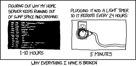
After about a week and a half, the python app crashes requiring a reboot. I rather like Randall Munroe's solution:


How did I know the python app was crashed? First, I was able to SSH into the Pi. This means that Wi-Fi and the Pi itself are both fine. Then I checked the running processes:

$ ps aux

This showed that the python app was no longer running. For some reason it quit on its own. Without running diagnostics, there's no real way to know.

So, rather than using a light timer, I changed the python app so that it performs only one reading and quits. Crontab now calls it every minute instead of once at reboot. 


$ sudo crontab -e

# m h  dom mon dow   command
  * *  *   *   *     sudo python /home/pi/Adafruit_Python_DHT/examples/ac_once.py


What could be done for more reliability? A diagnostic memory monitor for one. And also a regular reboot performed by crontab or maybe a light timer.

Tuesday, May 19, 2015

Air Conditioning on the Internet

IOT is the Internet Of Things. Not only are people using the Internet, but appliances and other devices are using the Internet too. Here’s how I put an air conditioner on the Internet.


This project remotely monitors the temperature of an air conditioning outlet vent. The purpose purpose is two-fold. The first is to make sure the room temperature is safe for my cat when I’m away.  The second is to identify air conditioner performance problems early on. When the air conditioner is off, the the vent temperature is a few degrees above the room temperature at floor level - where the cat lives when she’s not on top of the book case. When the air conditioner is on, the vent temperature minus the air conditioner set-point is a measure of the air conditioner performance. I found several posts from HVAC technicians who say that the outlet minus the inlet temperature of a properly functioning air conditioner should be 18 to 20 degrees F. I’m using the air conditioner’s thermostat set point as a proxy for the inlet temperature since the thermostat is near the inlet.


All measurements were made with a single DHT-22 temperature/humidity sensor sensor, available from Sparkfun or Adafruit. This sensor has a difficult non-standard one-wire interface, but fortunately Adafruit has a ready-to-go Raspberry Pi library on GitHub. They also have a wiring diagram to interface the DHT-22 to the Pi.


Here’s a condensation of the steps I used from the Adafruit tutorial.


Wire the sensor to the Pi as follows:

Sensor pin   PI pin   Function
1            1        Power
2            7        Data
4            6        Ground


Connect a 10K ohm resistor between sensor pins 1 and 2.

The pins are numbered from left to right when looking at the front of the sensor with the pins down.


The steps to download and install are as follows:

  1. git clone https://github.com/adafruit/Adafruit_Python_DHT.git
  2. cd Adafruit_Python_DHT
  3. sudo apt-get update
  4. sudo apt-get install build-essential python-dev
  5. sudo python setup.py install


To store this data with a minimum of effort, I took advantage of data.sparkfun.com which is a free service with an easy, well documented interface. The first thing needed to communciate with data.sparkfun.com is pycurl - an python interface to cURL. It's usually installed this way:

sudo pip install pycurl


But the install hit an error:

__main__.ConfigurationError: Could not run curl-config: [Errno 2] No such file or directory

StackOverflow provided an answer. This had to be done first:


sudo apt-get install libcurl4-openssl-dev

Now for the code. Just loop forever, constructing a URL and sending it once every minute:

pi@raspberrypi ~/Adafruit_Python_DHT/examples $ cat ac_vent03.py
#!/usr/bin/python
import time
import Adafruit_DHT
import pycurl
from StringIO import StringIO

sensor = Adafruit_DHT.DHT22
pin = 4

while True:
    humidity, temperature = Adafruit_DHT.read_retry(sensor, pin)
    temperature = temperature * 9 / 5 + 32
    if humidity is not None and temperature is not None:
        print 'Temp={0:0.1f}*F  Humidity={1:0.1f}%'.format(temperature, humidity)
        url = 'https://data.sparkfun.com/input/secret?private_key=anothersecret'
        url += '&temp=' + "{:.1f}".format(temperature)
        url += '&humidity=' + "{:.1f}".format(humidity)
        print url
        buffer = StringIO()
        c = pycurl.Curl()
        c.setopt(c.URL, url)
        c.setopt(c.WRITEDATA, buffer)
        c.perform()
        c.close()
        body = buffer.getvalue()
        print(body)
    else:
        print 'Failed to get reading. Try again!'
   
    time.sleep(60)


Next, we want this python app to start when the Pi reboots. This post in Raspberry Pi Spy was helpful in learning how to assemble a cron job that starts on reboot:


$sudo su
#crontab -e
@reboot sudo python /home/pi/Adafruit_Python_DHT/examples/ac_vent03.py &


To view the data, data.sparkfun.com has a tabular display, but I’m a nut for charts. Sparkfun has some nice examples of JavaScript that use the Google Chart API. Using those examples, I assembled the following HTML file which I saved to my local drive and open with a browser.
  
<!DOCTYPE html>
<html>
  <head>
    <!-- EXTERNAL LIBS-->
    <script src="https://ajax.googleapis.com/ajax/libs/jquery/1.11.1/jquery.min.js"></script>
    <script src="https://www.google.com/jsapi"></script>

    <!-- EXAMPLE SCRIPT -->
    <script>

      // onload callback
      function drawChart() {

        var public_key = 'secret';

        // JSONP request
        var jsonData = $.ajax({
          url: 'https://data.sparkfun.com/output/' + public_key + '.json',
          data: {page: 1},
          dataType: 'jsonp',
        }).done(function (results) {

          var data = new google.visualization.DataTable();

          data.addColumn('datetime', 'Time');
          data.addColumn('number', 'Humidity');
          data.addColumn('number', 'Temperature');

          $.each(results, function (i, row) {
            data.addRow([
              (new Date(row.timestamp)),
              parseFloat(row.humidity),
              parseFloat(row.temp)
            ]);
          });

          var chart = new google.visualization.LineChart($('#chart').get(0));

          chart.draw(data, {
            title: 'AC Vent','height':1024
          });

        });

      }

      // load chart lib
      google.load('visualization', '1', {
        packages: ['corechart']
      });

      // call drawChart once google charts is loaded
      google.setOnLoadCallback(drawChart);

    </script>

  </head>
  <body>
    <div id="chart" style="width: 100%;"></div>
  </body>
</html>


Here's the result. You can see temperature spikes down in an exponential curve when the air conditioner comes on.


This ran great for almost two weeks until it stopped posting data. Without thinking, I power-cycled the Pi. It started posting again, but I had no way to troubleshoot the failure. Did the app crash, did the Wi-Fi driver crash, or did the Pi run out of memory? Rather than having the app run continuously would it be better to have an app that only posts once and is triggered every minute by a cron job? In the next blog post, I'll write about troubleshooting and diagnostics for the internet of air conditioning.

Saturday, October 18, 2014

Software Defined Radio - A First Taste

I've been interested in Software Defined Radio for a while now, especially since cheap RTL28xx based dongle front-ends have become available. I ordered one on Amazon for $8 four weeks ago. Shipped directly from Shenzhen, it arrived this week. While I was waiting, I started investigating apps to control the radio. By far the most versatile tool appears to be GNU Radio; however, there's a bit of a learning curve for it. While I was waiting for my RTL dongle, I did some of the GNU Radio tutorial.

When my dongle arrived, I found that GNU radio doesn't have an RTL functional block by default. You can download and compile an RTL functional block, but I ran into difficulty which quickly became a rat hole. So plan B was to install every thing I thought might be useful. That kinda worked. Here's what I installed; all from the Ubuntu repositories.

GNU Radio -> apt-get install gnuradio grc
          to run ~$ /usr/bin/gnuradio-companion.
GR-OsmoSDR -> apt-get install gr-osmosdr
RTL-SDR -> apt-get install rtl-sdr
GQRX -> sudo add-apt-repository ppa:gqrx/releases (maybe)
        sudo apt-get install gqrx-sdr
        to run just ~$gqrx  


GQRX looked the most attractive app for a first try because it's like something one might assemble in GNU Radio. In fact it's based on GNU Radio. At first GQRX wouldn't start  because the Linux kernel had control of the radio. I found the fix here: https://opendesignengine.net/news/53, where it says to either

 run this before using the RTL:
    sudo rmmod dvb_usb_rtl28xxu 

Or, for a permanent fix, add this to /etc/modprobe.d/blacklist.conf

    blacklist dvb_usb_rtl28xxu

Once GQRX was started I found lots of static and no radio stations. It was time to try something more basic. I Googled one-line commands to play FM broadcast stations until I found one that worked.

 ~$rtl_fm -f 90.9M -s 192000 -r 48000 - | aplay -r 48k -f S16_LE -t raw -c 1

I found that adjusting orientation of the RTL's little antenna made a big difference.

Next I quit RTL-FM and restarted GQRX. After clicking and un-clicking the AGC button, FM stations appeared and I could move the dial across the spectrum and listen to the various stations.


Tuning on the VHF band with narrow-band FM demodulation is a little more tricky. Here the spectrogram is useful because the traffic is infrequent. You can see that there were two transmissions between 160.22 and 160.788 MHz that were missed because the tuning dial was not on them. Because they are on the spectrogram  the dial can be moved over them, and they can be listened to the next time they light up.


Sunday, September 14, 2014

Possum Power

I had initially hoped that the Rasberry Possum photo backup system could have used just one power pack. I found a "Y" adapter on Amazon that I thought would enable both the Pi and the hard drive to power power up from one adapter, thus enabling the use of an un-powered hub. Unfortunately this was not to be, as the Pi seemed to occasionally reboot in this configuration. We were getting down to the wire on this project, with only two days before our trip to Asia. The next best solution was a to use a powered hub for the hard drive, leaving a dedicated power source for the Pi. The diminutive Belkin F4U040 looked like a great solution. It's very compact, but were the power specs listed anywhere on the box; or on the Belkin website? No. I took a chance and bought one anyway, and was relieved that it was good for 100-240V - a true world power supply. To power the Pi I used an Amazon basics 2.1 A power pack.

Here's the interconnect diagram.

 And here's the Possum after backing up photos from an iPhone at Sun Moon Lake in Taiwan. We're using the iPad to telnet into the Pi to verify the that all the photos have been copied.


The Possum can also be managed from an iPod. I used Eric Maland's pTerm which worked very well. Also, we found that the ad-hoc network connection was very tenuous, so to keep it alive I used MochaSoft's Network Ping Lite.